Xerox WorkCentre 5685
Service Mode. GP10 How to Check a Motor
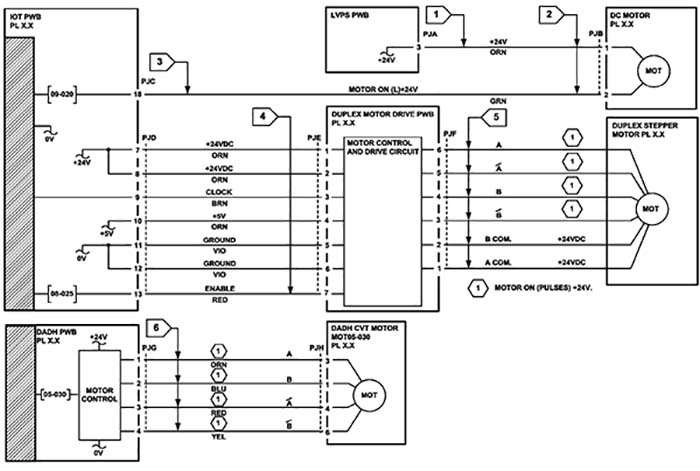
This procedure describes how to check the following motors:
- Two Wire DC Motors.
- Four Wire Stepper Motor
- Six Wire Stepper Motor.
Initial Actions
- Check that the motor is free to rotate.
- Check that all the motors mechanisms are clean, free to move and lubricated correctly.
- Enter the component control code for the motor, refer to dC330. If the motor does not run correctly, perform the appropriate procedure:
• Two Wire DC Motors.
• Four Wire Stepper Motor.
• Six Wire Stepper Motor
NOTE: The voltages, PJ numbers, pin numbers and PWB names shown are an example only. Go to the circuit diagram in the RAP for the correct information.
NOTE: For the motors supplied through the IOT PWB, refer to the OF7 IOT Diagnostics RAP.
Two Wire DC Motors
NOTE: In cases where the motor may be driven forward or backward, the same two feed wires are used, but the voltages on them are reversed, to reverse the motor direction. Such motors may have two component control codes, for forward and reverse. A typical application is a tray lift motor with a tray-up and a tray-down direction.
- Go to Flag 2. Disconnect PJB. Check that +24V is measured when the component control code for the motor is entered.
- Go to Flag 1. Disconnect PJA. Check for +24V on the LVPS.
- Go to Flag 3. Disconnect PJC. Check that the signal changes on the IOT PWB when the component control code for the motor is entered. • Check the wiring and the connectors for the motor circuit.
References:
- 01G +24V Distribution RAP.
- 01B 0V Distribution RAP.
- REP 1.2 Wiring Harness Repairs.
Four Wire Stepper Motor
NOTE: In some service manuals, the phase winding wires, A, /A, B and /B may be marked: A+, A-, B+ and B-, or as: phase A+, phase A-, phase B+ and phase B-.
- Go to Flag 6. Disconnect PJH. Check the motor on pulses on the harness when the component control code for the motor is entered.
- Go to Flag 6. Disconnect PJJ. Check the motor on pulses on the harness when the component control code for the motor is entered.
- Check the wiring and the connectors for the motor circuit.
References:
- 01G +24V Distribution RAP.
- 01B 0V Distribution RAP.
- REP 1.2 Wiring Harness Repairs.
Six Wire Stepper Motor
NOTE: In some service manuals, the phase winding wires, A, /A, B and /B may be marked: A+, A-, B+ and B-, or as: phase A+, phase A-, phase B+ and phase B-.
- Go to Flag 5. Disconnect PJF. Check the +24V supply and the motor on pulses when the component control code for the motor is entered.
- Go to Flag 4. Disconnect PJD. Check the +24V, +5V and 0V supplies.
- Go to Flag 4. Check the clock pulses.
- Go to Flag 4. Check that the signal on PJD pin 13 changes when the component control code for the motor is entered.
- Check the wiring and the connectors for the motor circuit.
References:
- 01G +24V Distribution RAP.
- 01E +5V distribution RAP.
- 01B 0V Distribution RAP.
- REP 1.2 Wiring Harness Repairs.