-
Catalog
-
Sign In
-
Contacts
-
Forum
-
Eng
Toshiba DP1810
Service Mode. 13 Test Mode
The operation of the following items can be checked in the test mode (13).
| Code |
Item |
Content |
| 01 |
SRAM test |
The read/write test is performed throughout the image memory. The test checks the whole SRAM. When an error is found, the address of the erroneous portion is displayed and the test is stopped. |
| 02 |
DRAM test |
The read/write test is performed on the DRAM. When an error is found, the address of the erroneous portion is displayed and the test is stopped. |
| 03 |
Image processing RAM test |
The read/write test is performed on the RAM used for the image processing. |
| 04 |
CODEC test |
The hardware test is performed on the CODEC block inside the SoC. The test encodes data of 10 lines using the MH coding, decodes it and compares it with the original data. |
| 05 |
ADF test |
Paper feeding, transporting and exiting are performed for originals. The number of the original sheets which exited is counted and displayed. |
| 06 |
Button test |
The buttons on the control panel are tested if they are operated properly. |
| 07 |
LED test |
All LEDs on the control panel are lit. |
| 08 |
FROM test |
The FROM is tested to see if it functions correctly. The checksum of the program data and function data stored in FROM is calculated and compared with the one reported in advance. |
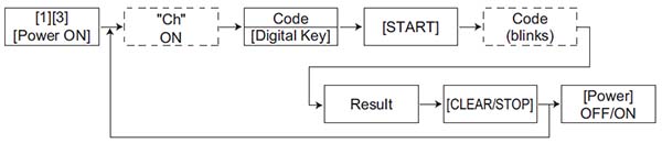
Key used in operation
Test result
| Code |
Item |
Result |
| Not abnormal |
Abnormal |
| 01 |
SRAM test |
The following display is lit on the 7- segment LED. |
The damaged memory address is displayed. The display can be shifted to 3 digits by the reproduction ratio button. |
| 02 |
DRAM test |
The following display is lit on the 7- segment LED. |
The damaged memory address is displayed. The display can be shifted to 3 digits by the reproduction ratio button. |
| 03 |
Image processing RAM test |
The following display is lit on the 7- segment LED. |
The following display is lit on the 7- segment LED. |
| 04 |
CODEC test |
The following display is lit on the 7- segment LED. |
The following display is lit on the 7- segment LED. |
| 05 |
ADF test |
The number of exiting sheets is displayed on the 7-segment LED. |
- |
| 06 |
Button test |
When all buttons are pressed and the [CLEAR] button is pressed, the following display is lit on the 7- segment LED. |
When all buttons are pressed and the [CLEAR] button is pressed, if it is not detected that all buttons are pressed, the following display is lit on the 7- segment LED. |
| 07 |
LED test |
All LEDs are lit. |
The abnormal LED is not lit. |
| 08 |
FROM test |
The following display is lit on the 7- segment LED. |
The following display is lit on the 7- segment LED. |
Notes:
- Before the ADF test (05) is started, make sure that the equipment has no abnormality and paper is set on the original tray.
- When the ADF test (05) is ready to start, “0” is displayed on the 7-segment LED and the [Start] lamp is lit. Pressing the [START] button starts the test.
- In the button test (06), the [ENERGY SAVER] and [CLEAR] buttons are not included. (When the [CLEAR] button is pressed during the button test (06), the display returns to the test mode in which the code can be entered.)
- In the LED test (07), the [ENERGY SAVER] lamp is not included.