Sharp MXM700U
Adjustment. 1-C Adjust the transfer current, voltage
NOTE:
Adjusting the output voltage requires the ability to measure internal impedance of 1000Ω. In addition, use high voltage probe together. (FLUKE87FLUKE80K-40 is recommended.)
Transfer voltage adjustment
| Item/ operation mode | Simulation | Adjustment voltage (monitor voltage) |
Connector | Pin # | Actual voltage /actual current |
||||
| Setting range | Default | ||||||||
| Front print | 8-6 | FRONT | 0 – 800 | 350 | – | – | – | 35±1.0µA (1.0 – 1.5Kv) | High voltage power PWB (MC/DV/TC) |
| 400 * | 40±1.0µA (2.0 – 2.5Kv) * | ||||||||
| Back print | BACK | 0 – 800 | 350 | – | – | – | 35±1.0µA (1.0 – 1.5Kv) | ||
| 400 * | 40±1.0µA (2.0 – 2.5Kv) * | ||||||||
| Transfer belt (cleaning) | 8-17 | SHV FRONT | 0 – 600 | 450 | – | – | – | AC4.5Kv (p-p) | |
| SHV BACK | 0 – 600 | 450 | – | – | – | AC4.5Kv (p-p) | |||
| THV- | 0 – 75 | 10 | DC – 100r10v | CN2 | 1 | DC –100±10v/AC4.5Kv (p-p) | |||
| Transfer roller (cleaning) | 8-18 | CRHV PLUS | 0 – 250 | 200 | +2.0±10.1v | – | Check pin | +2000±100v | High voltage power PWB (TC cleaning) |
| Transfer roller (print) | CRHV MINUS | 0 – 250 | 200 | –2.0±10.1v | – | Check pin | –2000±100v | ||
Transfer voltage adjustment (print operation mode)
This adjustment is needed in the following situations:
- The high voltage power PWB (MC/DV/TC) has been replaced.
- U2 trouble has occurred.
- The PCU PWB has been replaced.
- The EEPROM of the PCU PWB has been replaced.
- Go through the modes specified in Simulation 8-6.
- Select the number that corresponds to the adjustment item (FRONT/BACK) using the numeric keypad.
- Press the Start key.
- Enter the adjustment value (default) using the numeric keypad.
- Press the Start key. (The adjustment value is put into memory, and the corresponding current is output for 30 seconds.) The operation can be stopped with the SYSTEM SETTINGS key.
NOTE: It is not possible to determine the adjusted transfer voltage (print operation mode) (FRONT/BACK). If the voltage seems to be abnormal after setting the default value, therefore, the high voltage PWB (MC/DV/TC) should be replaced.
Transfer voltage adjustment (transfer belt cleaning mode)
This adjustment is needed in the following situations:
- The high voltage power PWB (MC/DV/TC) has been replaced.
- U2 trouble has occurred.
- The PCU PWB has been replaced.
- The EEPROM of the PCU PWB has been replaced.
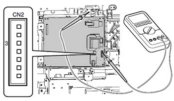
- Remove the rear cover of the machine.
- Apply a digital multi-meter to the connector CN2 pin (1) of the high voltage PWB and the chassis GND.
- Go through the modes specified in Simulation 8-17.
- Select the number that corresponds to the adjustment item (SHV FRONT / SHV BACK) using the numeric keypad.
- Press the Start key.
- Set each adjustment item to the default value (enter the adjustment value and then press the Start key).
* The adjustment items (SHV FRONT / SHV BACK) correspond to the AC component of the 'transfer belt cleaning mode voltage' applied to the transfer roller, but this voltage component cannot be determined. If the voltage seems to be abnormal after setting the default adjustment value, therefore, the high voltage PWB (MC/DV/TC) should be replaced. - Select the number that corresponds to cleaning operation mode (THV-) using the numeric keypad.
* The adjustment items (THV-) corresponds to the DC component of the 'transfer belt cleaning mode voltage' applied to the transfer roller. - Press the Start key.
- Press the Start key to have the voltage output for 30 seconds. If the output voltage is not within the requirement, do the following steps. The operation can be stopped with the SYSTEM SETTINGS key.
- Enter the adjustment value using the numeric keypad.
- Press the Start key. (The adjustment value is put into memory, and the corresponding voltage is output for 30 seconds.)
Repeat steps 10 to 11 until the output requirement is satisfied.