Konica-Minolta bizhub C3320i
Troubleshooting. IQ. White line 2, white band 2, color line 2, color band 2
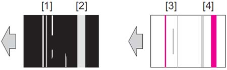
- White line
- White band
- Color line
- Color band
Initial troubleshooting procedure
| Step | Section | Check item | Result | Action |
|---|---|---|---|---|
| 1 | Paper Setting | The paper to be used for printing does not match the paper type and size of paper setting selected on the machine. | YES | Make the paper setting again on the machine. |
| 2 | Service Mode -> Stabilizer | Select [Service Mode] -> [Imaging Process Adjustment] - > [Stabilizer] -> [Stabilization Only] and the image trouble is eliminated. |
NO | Go to the next step. |
| 3 | Service Mode -> Gradation Adjust | Select [Service Mode] -> [Imaging Process Adjustment] - > [Gradation Adjust] and the image trouble is eliminated. |
NO | Go to the next step. |
| 4 | Image check | • Select [Service Mode] -> [Test Mode] -> [Halftone Pattern]. Select "SINGLE", "HYPER", "Error diffusion", "1- Sided", "CMYK", and "Full Bleed", enter "64" for Density, and load tray 2 with A3 paper. Press the start key. This runs a print cycle for C, M, Y, and K in that order. • Check the image after printing to determine which color causes the abnormal image. |
1 to 3 colors | Go to the 1-color troubleshooting procedure. |
| 4 colors | Go to the 4-color troubleshooting procedure. | |||
| None | Go to scanner troubleshooting procedure. |
1-color troubleshooting procedure
| Step | Section | Check item for the faulty color | Result | Action for the faulty color |
|---|---|---|---|---|
| 1 | Write section | Sharp white line or colored line is blurry. | YES | Clean the PH window. |
| 2 | Charging section | Foreign matter on charging roller. | YES | Lightly wipe the surface clean of foreign matter using hydro-wipe (65AA-99##). Note: Do not apply a strong force to the surface of the charging roller, as doing so can damage the surface. |
| 3 | Photoconductor section | There is a positive contact between the electrostatic charger application terminals and the high voltage unit connection terminals. | NO | Clean or correct the terminal. |
| 4 | Developing section | There is a positive contact between the developing bias application terminals and the high voltage unit connection terminals (Y: B4; M: B3; C: B2; K: B1). | NO | Clean or correct the terminal. |
| 5 | Photoconductor section | Scratches on photoconductor. | YES |
|
| 6 | Photoconductor section | Toner line or dirt on photoconductor. (improper cleaning) | YES | Replace the drum unit. |
| 7 | 1st transfer section | There is a positive contact between the transfer belt application terminals and the high voltage unit connection terminals (Y: T1-4; M: T1-3; C: T1-2; K: T1-1). | NO | Clean or correct the terminal. |
| 8 | 1st transfer section | Scratches or dirt on 1st transfer roller. | YES |
|
| 9 | Developing section | Toner bristles not even on the developing roller, resulting in a line or band. | YES | Replace the developing unit. |
| NO |
|
4-color troubleshooting procedure
| Step | Section | Check item | Result | Action |
|---|---|---|---|---|
| 1 | Paper path | There is dirty or foreign matter on paper path. | YES | Check or clean the paper path including the duplex section. |
| 2 | Transfer belt unit | Lines that can be removed by cleaning are evident on the transfer belt. (improper cleaning) | YES |
|
| 3 | Transfer belt unit | Dirt, scratches, or foreign matter on the transfer belt. | YES |
|
| 4 | Transfer belt unit | There is a positive contact between the transfer belt application terminals and the high voltage unit connection terminals (Y: T1-4; M: T1-3; C: T1-2; K: T1-1). | NO | Clean or correct the terminal. |
| 5 | 2nd transfer section | Dirt or foreign matter on the 2nd transfer roller. | YES |
|
| 6 | 2nd transfer section | There is a positive contact between the application terminals of the 2nd transfer and the connection terminals (T2, E1) and ground terminal of the high voltage unit. | NO | Clean or correct the terminal. |
| 7 | Fusing unit | Dirt or foreign matter on paper path or separation claw of the fusing unit. | YES | Clean. (Disassembling the fusing unit is prohibited.) |
| 8 | Fusing unit | Scratches on belt or roller in fusing unit. | YES | Replace the fusing unit. |
| NO |
|
Scanner troubleshooting procedure
| Step | Section | Check item | Result | Action |
|---|---|---|---|---|
| 1 | Original | Original is damaged or dirty. | YES | Change the original. |
| 2 | Original Type | Select [Copy] -> [Original Type] and change the setting, and the image trouble is eliminated. | YES | Correct the setting. |
| 3 | When original glass is being used: Service Mode -> Scan Area |
Select [Service Mode] -> [Machine] -> [Scan Area] -> [Image Position: Leading Edge] and make the necessary adjustment, and the image trouble is eliminated. | NO | Go to the next step. |
| 4 | When original glass is being used | Original glass or original pad is dirty. | YES | Clean. |
| NO | Replace the CCD unit. | |||
| 5 | When DF is being used: 1st side: End face of original is reproduced as a line | Select [Service Mode] -> [ADF] -> [Auto Stop Position Adjustment] -> [Main Scanning (Front)] and the image trouble is eliminated. | NO | Go to the next step. |
| 6 | When DF is being used: 2nd side: End face of original is reproduced as a line | Select [Service Mode] -> [ADF] -> [Auto Stop Position Adjustment] -> [Main Scanning (Back)] and the image trouble is eliminated. | NO | Go to the next step. |
| 7 | When DF is being used: 1st side | Document reading glass or document reading glass cleaning brush is dirty. | YES | Clean. |
| NO | Replace the CCD unit. | |||
| 8 | When DF is being used: 2nd side | CIS glass or CIS cleaning brush is dirty. | YES | Clean. |
| NO | Replace the CIS module. |