Canon i-SENSYS MF645Cx
Troubleshooting. Items
Recurring faulty image
Overview
Foreign matters or lines on rollers along the paper feed path may cause faulty images in the vertical scanning direction.
Field Remedy
See the roller pitches listed in the tables below to clean and/or replace the corresponding parts.
CAUTION: Since the Primary Charging Roller, Photosensitive Drum, and Developing Roller are located inside the cartridge and cannot be cleaned, replace the cartridge.
| Roller pitch | Parts |
|---|---|
| Approx. 44 mm | Registration Roller |
| Approx. 51 mm | Secondary Transfer Roller |
| Approx. 19 mm | Primary Charging Roller |
| Approx. 63 mm | Photosensitive Drum |
| Approx. 31 mm | Developing Roller |
| Approx. 57 mm | Fixing Roller |
| Approx. 57 mm | Pressure Firm |
Confirming nip width
Overview
Although the nip width of the Fixing Assembly cannot be adjusted with this machine, it can be checked.
By checking the nip width when fixing failure occurs, it is possible to judge whether there is a problem with the Fixing Assembly.
Field Remedy
Check the nip width of the Fixing Assembly by the following procedure.
- Print a solid black image on an A4/LTR size paper using the cartridge of this machine and bring it to the customer site.
- Load the solid black printed paper with its printing side facing down in a cassette of the machine.
- Use an external device to print a solid white image.
- Open the Front Cover after approx. 25 seconds, leave it for 10 seconds or more, and then take out the printed paper.
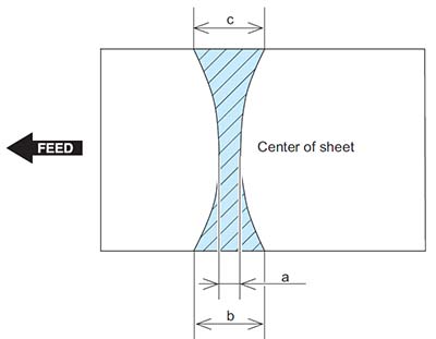
- Measure the widths of the glossy part of the toner on the printed paper, and check that they are within the range as follows.
• Center (a): 6.0 to 8.1 mm
• Edge (b) and (c): 6.3 to 8.5 mm each
• Difference between left and right ( | b - c | ): 1.0 mm or less
Action When Hue Differs between the Front and Back Sides of the Output Image at Duplex Copy (For the duplex scanning ADF model)
Overview
If hue differs between the front and back sides of the output image when making a copy of 2-sided original, perform color difference correction on both front and back sides.
Field Remedy
Follow the procedure shown below to perform color difference correction.
- Execute full adjustment of auto gradation adjustment. (Adjustment of density of the printed output)
Adjustment/Maintenance > Adjust Image Quality > Auto Adjust Gradation > Full Adjust - Output PG-TYPE 26 from test mode in service mode.
• TESTMODE > PRINT > PG-TYPE - Read the chart using the duplex scanning model (front side).
Place the chart PG-TYPE 26 output in test mode on the ADF with the printed side facing up and execute the following service mode.
• COPIER > FUNCTION > MISC-R > 1PSCLB-A - Read the chart using the duplex scanning model (back side).
Place the chart PG-TYPE 26 output in test mode on the ADF with the printed side facing down and execute the following service mode.
• COPIER > FUNCTION > MISC-R > 1PSCLB-B - Judgment
Check that the following service mode values are 1 (reading succeeded).
• COPIER > DISPLAY > CCD > 1P-ERR-A
• COPIER > DISPLAY > CCD > 1P-ERR-B
If any value other than 1 (reading succeeded) is displayed, turn OFF and then ON the power of the host machine and read the chart again.