Xerox WorkCentre 5685
Service Mode. GP13 How to Check a Switch
Description
Use this procedure to check the operation of a switch.
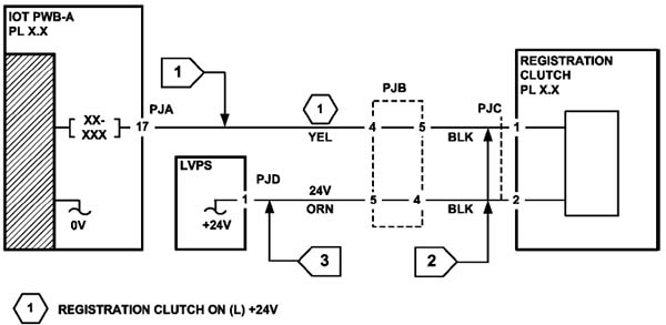
NOTE: The circuit in Figure 1 shows an interlock switch activated by the closing of a door.
Initial Actions
Manually check that the switch operates. Ensure that the magnet or other actuator has enough mechanical movement to operate the switch.
NOTE: The voltages, PJ numbers, pin numbers and PWB names shown are an example only. Go to the circuit diagram in the RAP for the correct information.
Procedure
- Go to Flag 1. Disconnect PJA. Check the electrical operation of the switch.
- Go to Flag 1. Disconnect PJB. Check for +5V and 0V on the IOT PWB.
- Go to Flag 1. Check the wiring and the connectors for the switch circuit.
References:
- 01B 0V Distribution RAP
- 01E +5V Distribution RAP.
- REP 1.2 Wiring Harness Repairs.