Riso ComColor GD9631
Ink Flow Section. Basic Structure
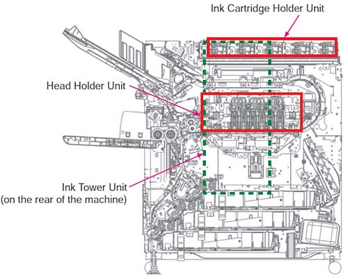
The Ink Flow Section is composed of the Head Holder Unit, Ink Cartridge Holder Unit, and Ink Tower Unit. This section supplies ink from the Ink Cartridges, circulates the ink, and edrops the ink from the Print heads.
Ink Cartridge Holder Unit
| Part Name | Function | Type |
|---|---|---|
| Ink Supply Valve | Supplies ink in the Ink Cartridge to the Negative Pressure Ink Tank | Solenoid Valve |
| Cartridge Joint | Connection between the Ink Cartridge and ink path | Joint |
| Ink Release Cam | Pushes the Cartridge Joint to connect with the Ink Cartridge | Cam |
| Cam Motor | Rotates the Ink Release Cam | DC motor |
| Cartridge Pan | A pan-shaped channel that collects ink that overflows from the Ink Cartridges and drains it down towards the Waste Ink Tank | |
| Joint Spring | The spring that pushes away the Cartridge Joint when the Ink Cartridge is removed | Spring |
| Holder Bottom Plate | Bottom guide when inserting and removing Ink Cartridges |
Ink Tower Unit
| Part Name | Function | Type |
|---|---|---|
| Pressurized Ink Tank | Sends ink to the Head with the pressure in the Pressurized Ink Tank and circulates the ink | ― |
| Negative Pressure Ink Tank | Collects ink from the Head with negative pressure | ― |
| Pressurized (Negative Pressure) Ink Tank Ink Level Detection Sensor | Detects the ink level in the Pressurized (Negative Pressure) Ink Tank | Reed switch |
| Pressurized (Negative Pressure) Ink Tank Common Air Chamber | Connected to the Pressurized (Negative Pressure) Ink Tanks to supply the common pressure | ― |
| Positive (Negative) Pressure Sensor | The sensors that measure the air pressure in the Pressurized (Negative Pressure) Ink Tank Common Air Chamber | Pressure sensor |
| Pressurized (Negative Pressure) Ink Tank Air Valve | Vents and seals the positive pressure (negative pressure) side | 3-way solenoid valve |
| Positive (Negative) Pressure Regulator Valve | Finely adjusts the positive pressure (negative pressure) side pressure | 3-way solenoid valve |
| Ink Circulation Pump | Sends ink from the Negative Pressure Ink Tank to the Pressurized Ink Tank | Piston pump |
| Air Pressure Regulator Pump | Located between the Pressurized (Negative Pressure) Ink Tank Common Air Chambers and generates positive and negative pressure using power | Diaphragm pump |
| Air Flow Rate Regulator Valve | Adjusts the air flow rate when pressure is generated by the Air Pump |
3-way solenoid valve |
| Ink Filter | Located in the Pressurized Ink Tanks and removes foreign particles mixed in the ink | Filter |
| Air Filter | Prevents foreign particles from being mixed in the ink flow system | Filter |
| Heat Sink | An aluminum alloy passage that cools the ink through heat dissipation | ― |
| Ink Cooling Fan | Lowers the temperature of the ink by cooling the Heat Sink | Fan |
| Ink Heater | Heats the ink heading from the Pressurized Ink Tank to the Ink Bus | AC heater |
| Heater Temperature Sensor | Installed in the Ink Heater to detect the temperature of the Heater | Thermistor |
| Ink Temperature Sensor | Located at the exit of the Ink Heater to detect the temperature of the ink | Thermistor |
| Overflow Pan | Located at the bottom of the Ink Flow Section to receive overflow ink |
― |
| Overflow Ink Level Detection Sensor |
Located in the Overflow Pan to detect overflows | Reed switch |
Head Holder Unit
The Head Holder Unit is primarily composed of the following subunits.
- Print Head
- Ink Bus
- BP Elevation Mechanism and Head Gap Adjuster Mechanism
- Paper side edges and top and bottom edge detection
- BP Contact Detection Mechanism